Reviews
No reviews found
Description
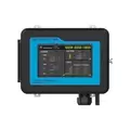
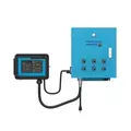
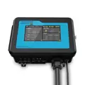
The Master Environmental Control C-1 offers convenient and efficient management of various environmental parameters within the same greenhouse.
Specifications:
- Input Voltage:
- 120VAC +- 15VAC, 60Hz, 1A (Customizable)
- 220VAC +- 15VAC, 50/60Hz, 1A (Customizable)
- AC Signal Output (Port):
- 10-Channel signal Output: AC24V/0.1A
- Other Signal Output Ports (RJ12):
- RJ12 x 4, 4-Channel RS485 communication
- Signal line output: DC24V, 1.0A
- Network Port: RJ45
- Dimensions: 14" H x 17" W x 4" D (excluding length of power cable)
- Power Cord Length: 2m / 6.5 Ft.
- Net Weight: 9.5 Lbs / 4.30 Kgs
- Gross Weight: 10.5 Lbs / 4.76 Kgs
- Package Size: 24.4x24.4x34.3 in / 620x620x870mm
Accessories:
- Self-tapping screws x4
- Ring Expansion Screws x4
- Temperature and humidity sensor probe x1
- AC Station module x1
- RJ12 network extension connector x1
- RS485 communication extension cable 5.0m x1
Included in the Box:
- CO2 Humidity & Temp Sensor
- Humidity & Temp Sensor
- Gas Detected: CO2
- Working Voltage: DC24V
- Working Current: <10mA
- Humidity Range: 0-100%RH
- Humidity Accuracy: +-2%RH
- Temperature Range: 0-70*C
- Temperature Accuracy: +-0.5*C
- Maximum Quantity: 4 pcs per set
- Communication Mode: RS485 (Modbus-RTU)
- Light Sensor: Photocell
- AC Station Socket Module
- Light Control Module
- Input Voltage: AC110V 60Hz
- Output Voltage: 0-10V(DC)
- Maximum Power: <1100W
- Communication Terminal: RJ12 connector
- Indicator: Green LED
- Max. Connections per Channel: 20 pcs.
- Max. Connections Quantity: 32 Pcs.
- Communication Mode: RS485 (Modbus-RTU)
Basic Configuration:
In a standard working environment with a grow area of 200m3, the following equipment is recommended:
- 1 Master Environmental Control C-1 (Master Controller)
- 1 CO2 4 in 1 sensor (Monitoring CO2 parameters, relative temperature value, relative humidity value, and light parameters)
- 1 Temperature, humidity, and light 3 in 1 sensor (Monitoring relative temperature value, relative humidity value, and light parameters)
- 1 AC Station module (Used to control the CO2 output device - TANK or generator)
- 2 LDA-1 light control modules (Used to control the main light line and auxiliary light line)
- Several RS485 cables (Extension lines for connecting each terminal)
Note:
Before installation, users should consider the number of sensors and related devices based on the actual conditions of the planting area. Heavy-current (110V-380V) devices in the circuits should be installed in the distribution box first.
Connection Guide:
- Connect the sensor module to the Sensor port in series.
- Connect the AC Station socket module to the Device port in series.
- Connect the LDA-1 light control module to the LINE-1 port for the main light control line.
- Connect the LDA-1 light control module to the LINE-2 port for the auxiliary light control line.
- Connect the internal 10-channel port to the corresponding configuration in the distribution box or related equipment that supports AC24V signals.
- Before connecting, check if the positive and negative poles of the output line are correct.
- After the circuit connection is completed, plug in the power and turn on the device.


